
Interactive project map: nine projects, one small city
Nine projects, one small city. Hover or tap a marker to discover more
Where I would start
About

I’m Marta, a Mechanical Engineer specialising in Product Design. I’m finishing my MEng at UC Berkeley in May 2027, after a BEng at the University of Bristol.
I want to design the things people live with every day: products that are creative, functional, ergonomic and aesthetically pleasing. Engineering comes first, with mechanisms, features, fit and materials. Then colour and finish help people use the product and enjoy it.
My favourite stage is concept design: making an idea do exactly what I want, efficiently, within tight constraints. It’s where I get most creative. I take ideas from sketches to CAD, FEA and 3D-printed prototypes, and I check them with models and prints before I trust them. I work in Autodesk Fusion and Siemens NX for CAD, Abaqus and NX for analysis, and FDM and resin printing for prototypes.
I’m Portuguese and speak English, Spanish and a little French.
Off the clock: tennis, padel, planning the next trip and a phone full of invention ideas.
Tools Autodesk Fusion, Siemens NX, Abaqus, FDM and resin 3D Printing, Laser Cutting, Python, MATLAB, Arduino.
- MEng, UC BerkeleyMechanical Engineering, Product Design. Aug 2026 to May 2027.
- BEng, University of BristolMechanical Engineering, GPA 3.58, 2023 to 2026.
- Bristol PLUS AwardGiven to under 5% of students.
- Portuguese SocietyRe-established it after 3 years and grew it to 45 members.
Let’s build physical products people use daily!
I’m currently looking for full-time Mechanical or Product Design Engineering roles starting Summer 2027.
Berkeley, California
Experience
Industry placements and leadershipIndustry placements
- Jun to Jul 2025
Logoplaste
Innovation Lab Intern · Cascais, Portugal
- Tested six recycled plastic samples for density, viscosity, moisture, purity and colour against the supplier quality specifications. Three passed and were cleared for reuse in packaging.
- Worked across the Design, CAD/FEA, Quality, Moulds and Trials teams, and visited two plants to see extrusion and injection moulding at high volume.
- Ran a biomimicry analysis of ticks, found five useful properties and proposed uses in medical adhesives and inflatables.
- Organised over 100 Migration Test documents from 68 plants so the Raw Materials team could find and trace them.
- May 2026
Matter
Microplacement Student · Bristol, UK
- Completed a design engineering technical challenge, usually reserved for full-time candidates, modelling a rotating sprinkler system.
- Shadowed engineers to learn how the filtration products work and how the company runs.
- Jun to Aug 2024
TAP Air Portugal
Aircraft Engine Maintenance Shop Intern · Lisbon, Portugal
- Compiled LEAP-1A maintenance procedures so the shop could assess the licences and capability needed to service that engine.
- Shadowed technicians through the full engine overhaul cycle (CFM56, LEAP-1A/-1C), and its tools and workstations.
Leadership and campus
- Sep 2024 to May 2026
University of Bristol Students' Union
Co-Founder & Treasurer, Portuguese Society · Bristol, UK
- Re-established the society after a 3-year hiatus, growing it to 45 students and earning Bronze Accreditation from the Students' Union.
- Secured a £100 grant, doubled the budget and negotiated a sponsorship with a local club.
- Aug 2025 to Jan 2026
University of Bristol
Peer Mentor · Bristol, UK
- Mentored 3 first-year students through academic and social onboarding, advising on course priorities, syllabus navigation, and day-to-day university life.
Let’s build physical products people use daily!
I’m currently looking for full-time Mechanical or Product Design Engineering roles starting Summer 2027.
Berkeley, California
Marta David Nunes
Mechanical and Product Design Engineer
MEng Mechanical Engineering (Product Design), UC Berkeley · BEng Mechanical Engineering, University of Bristol
Mechanism design, CAD (Autodesk Fusion, Siemens NX), structural FEA (Abaqus, Siemens NX) and rapid prototyping with 3D printing.
- 2nd of 5 finalists, The CAD Challenge 2026 (hands-free page turner)
- Winner, UC LAUNCH Launch-a-thon 2026 (1 of 4 winning teams out of 23)
- Graduating May 2027 · seeking full-time Mechanical and Product Design Engineering roles
Highlights
The three projects I would start with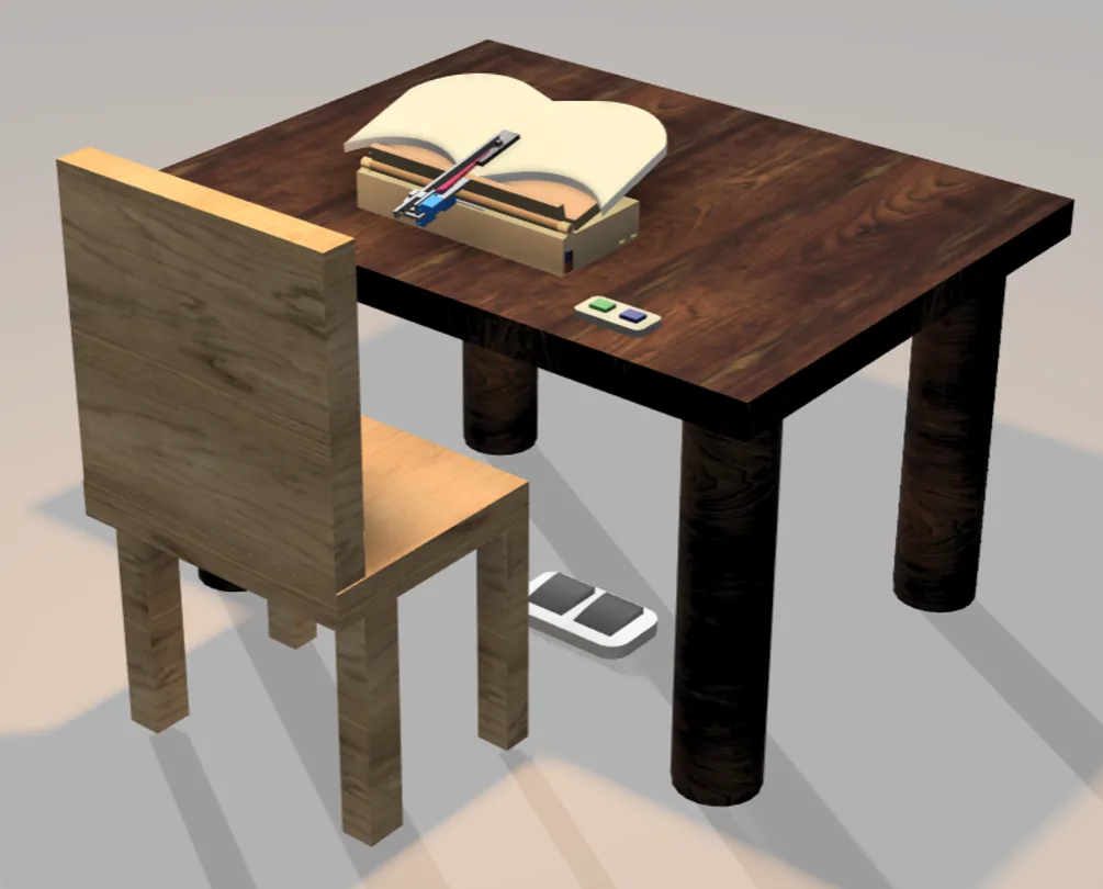 2nd place, The CAD Challenge 2026
Hands‑Free Book Page Turner
- Problem
- People with limited hand dexterity cannot turn a page, and automatic page turners cost $2,000 to $3,000.
- My part
- Owned the concept and its functions, apart from the electroadhesive page separator. Modelled the base, tilting back and on/off button, and produced the drawings, exploded view and BOM.
- Design decisions
- Designed to be injection moulded in ABS. The base is two halves, so the tilter and back drop in before they are joined, and the pad and servos are off the shelf.
- Result
- 2nd of five finalists at The CAD Challenge 2026, with an internship interview at Hestus.
 Final-year project, Bristol
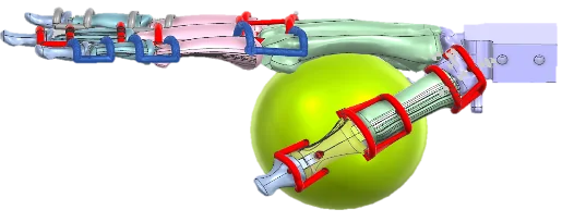
Anthropometric Tendon-Driven Prosthetic Hand
- Problem
- Myoelectric hands cost £25,000 to £60,000; printed hands are cheap but need a passive way to open the fingers again.
- My part
- Led the printing and testing of elastic extensors, redesigned the MCP extensor and simulated two torsion spring designs in Siemens NX.
- Design decisions
- Moved from elastic resin to TPU, then used the simulation to find why TPU did not restore the finger, and simulated two torsion spring designs to see whether they open it.
- Result
- Failure diagnosed in simulation, and both torsion spring designs open the finger in simulation.
 Applied Solid Mechanics, Bristol
Pressure Vessel Lifting Lug
- Problem
- Can a welded lifting lug carry its share of a 12-tonne pressure vessel, and how often must it be inspected?
- My part
- Built the hand model, checked it in Abaqus, searched for the worst off-axis pull and proposed the inspection interval.
- Design decisions
- Checked the weld and the eye separately, used the worst off-axis pull instead of the straight pull, and let fracture mechanics set the inspection interval.
- Result
- Yield-to-stress ratio of 5.6 at the weld and 2.7 in the eye. Inspection proposed every 10⁵ cycles.
All work
The rest, newest first. Each card opens its full design process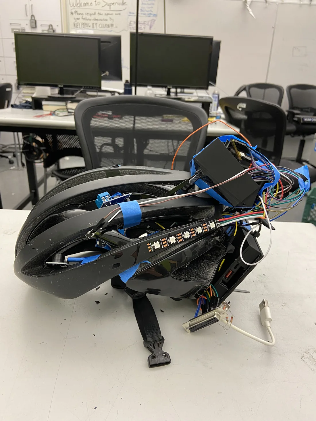 CalHacks 13.0 hackathon
Smart Bike Helmet
- Problem
- Cyclists who check a phone for directions take their eyes off the road. We built a retrofit helmet in one weekend that signals turns, shows a brake light and cues directions with buzzers.
- My part
- I designed and 3D printed the two housings and designed the app’s UI/UX in Figma. I also edited and narrated the demo video.
- Design decisions
- I measured the helmet with calipers and mounted the housings at the back, with a 50° angle between the two boxes to follow the curve. The electronics box went to a second version with mounting eyelets, printed in a 5-hour window.
- Result
- A working demo helmet, shown at CalHacks, with left, front and right buzzer cues.
 Concept design, Bristol
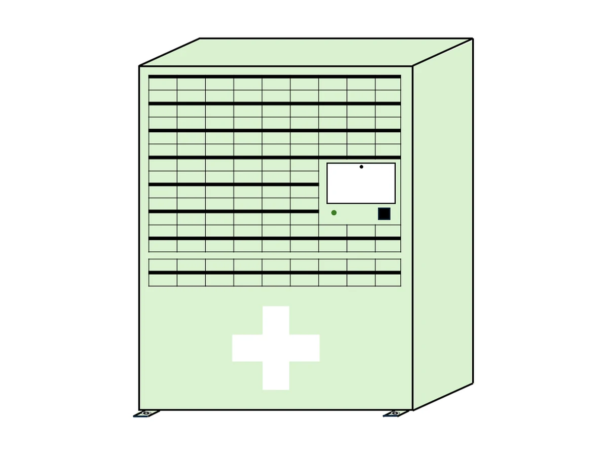
MedUp Prescription Pick-Up Locker
- Problem
- Pharmacies cut their opening hours, so working people struggle to collect prescriptions.
- My part
- Ran concept selection with four Pugh matrices, then sized the drawers, cooling, backup battery and materials.
- Design decisions
- Sized the cooling and the battery together: 13 W leaks into the cold section, so the compressor runs about 4% of the time, and a 12 V LiFePO4 battery covers a 3-hour power cut.
- Result
- A supermarket locker concept of 120 drawers, 18 of them refrigerated.
 Heat Transfer, Bristol
Tent Thermal Management
- Problem
- Keep two sleepers at 19 °C in a thin tent on a −2 °C night without adding much mass or complexity.
- My part
- Modelled conduction, convection and radiation for a two-person tent by hand.
- Design decisions
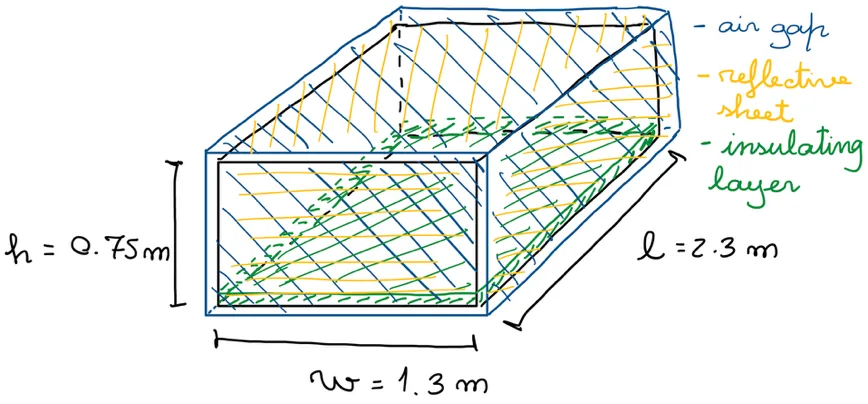
- Modelled the tent as a box and listed 27 assumptions, most leaning to the worst case. Chose three passive fixes that need no power.
- Result
- The three fixes cut the 3.9 kW of heating needed by 82%, to 706 W, which still needs a heater.
 Engineering Practice, Bristol
Solar Panel Deployment Mechanism
- Problem
- Can a car roof box hold six solar panels that deploy themselves on one DC motor and face the sun?
- My part
- Led a team of four. Wrote the 42-requirement specification, built three of the four LEGO concepts and designed the failsafe automation.
- Design decisions
- Compared the concepts in LEGO, then tuned the link lengths and mounting angles of the chosen one so the panels face the sun.
- Result
- It met all but one key requirement in the calculations: 8.17 kg against a 30 kg limit and a 10.65 s deployment. The packed height was too tall.
In progress
- Know moreMEng capstone, in progress
Automated MOF Deposition Rig
A rig that automates depositing a metal-organic framework (MOF), a porous carbon-capture material, designed as a team of three. I lead the assembly design. Details are confidential for now.
- Know moreDesign for the Human Body, in progress
Assistive Drinking Device
A project exploring how people with limited hand strength or motor control could drink with less help, while keeping their dignity. Team of five; concepts come next.
Other projects
 Winner, UC LAUNCH Launch-a-thon
BlueRobins Newsletter
- Problem
- BlueRobins wanted a newsletter parents would read to the end: short, and made for a phone.
- My part
- Chose and sketched the five sections, proposed the quiz, made the wireframe and presented the pitch video.
- Design decisions
- Five short sections that read in two to three minutes on a phone, with a quiz section I proposed.
- Result
- Winner of the UC LAUNCH Launch-a-thon 2026, one of 4 winning teams out of 23.
 Website
What to Wear Website
- Problem
- Deciding what to wear depends on the weather, how you feel the cold and what you own.
- My part
- Decided every feature and how the website works. AI wrote all the code.
- Design decisions
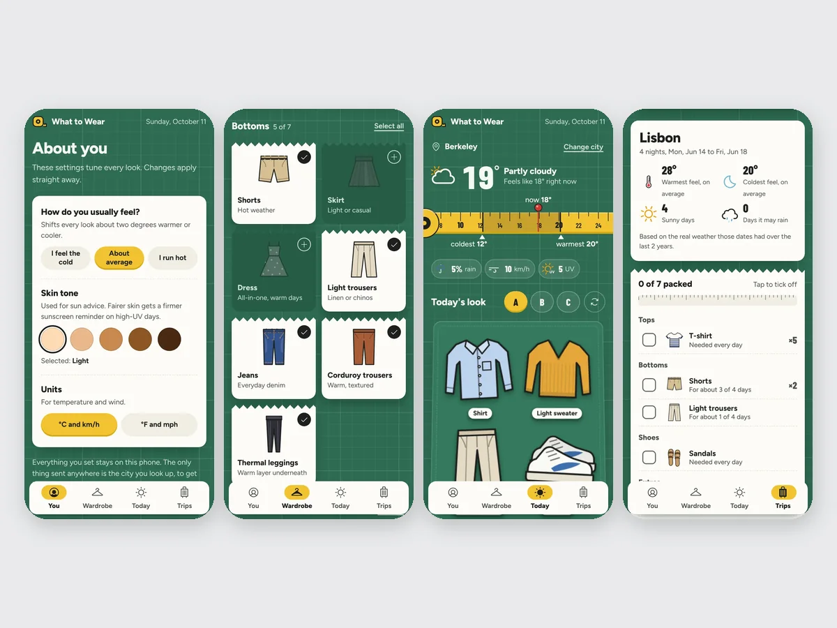
- Four tabs, You, Wardrobe, Today and Trips. Outfits come from the weather, your body and your wardrobe, and a trip becomes a packing list.
- Result
- A working website, shown here in screenshots with sample data.
Let’s build physical products people use daily!
I’m currently looking for full-time Mechanical or Product Design Engineering roles starting Summer 2027.
Berkeley, California
Smart Bike Helmet
A retrofit bike helmet that signals turns, shows a brake light and cues directions with buzzers, built in one weekend. I designed and 3D printed its two housings and designed the app’s UI/UX.
Team of 4 · weekend prototype · I designed the housings and the app’s UI/UX
- Problem
- Cyclists who check a phone for directions take their eyes off the road. We built a retrofit helmet in one weekend that signals turns, shows a brake light and cues directions with buzzers.
- My part
- I designed and 3D printed the two housings and designed the app’s UI/UX in Figma. I also edited and narrated the demo video.
- Design decisions
- I measured the helmet with calipers and mounted the housings at the back, with a 50° angle between the two boxes to follow the curve. The electronics box went to a second version with mounting eyelets, printed in a 5-hour window.
- Result
- A working demo helmet, shown at CalHacks, with left, front and right buzzer cues.
Directions without taking your eyes off the road
Riders who follow a map on a phone look away from the road. In one weekend at CalHacks 13.0, we built a retrofit helmet that cues directions and signals to the people around the rider.
- Directions by buzzerThree buzzers, left, front and right, cue which way to turn.
- Blinkers and brake lightThe blinkers switch on automatically from the GPS signal, and a brake light shows at the back.
- Voice navigationA button and microphone on the helmet take a spoken destination, such as “navigate me to…”.
- A companion appA map and destination search, with the trips kept in a database.
My part was the two housings, the app’s UI/UX and the demo video, on the next tabs.
Housings for flat electronics on a curved helmet
I designed and 3D printed the helmet’s two housings: one for the power bank and one for the microcontroller circuit. The central design question was how to mount flat electronics on a curved helmet, so I designed planar boxes and chose their position and angle from caliper measurements.
- Measured firstI measured the helmet and the electronics with calipers, and worked out the 50° angle between the boxes from those measurements.
- Mounted at the backI weighed the top against the back and chose the back, because I expected it to disturb the airflow less.
- Two boxes, with slotsA power bank box and an electronics box. The electronics box has one slot for the cables from the power bank and one for the cables to the buzzers, microphone, LEDs and button.
- Two versionsVersion 1 of the power bank box and version 2 of the electronics box ended up on the helmet. Version 2 added mounting eyelets and was printed on Bambu Lab printers in a 5-hour window.
The electronics box was sized for an Arduino that joined the circuit late, because the blinkers ran at 5 V and the ESP32 at 3.3 V.
From paper sketch to app screens
I designed the app’s UI/UX: a paper sketch and feature list first, then the pages, palette, icons and flow in Figma. I refined its animations by vibe coding.
The sketches
The screens
- Sketch and feature listI started from a paper sketch of the app and a list of the features.
- Pages and flowThe pages and the transitions between them, including the GO transition into the ride screen.
- Palette and iconsA dark screen with a yellow accent, and icons for the rider’s bicycle or scooter.
- AnimationsI refined the animations by vibe coding, including the transition into the ride screen, to polish the interaction.
The demo video, and what I learned
What I learned
- Retrofit means fitting flat electronics to a curved helmetThe helmet surface is curved, but the circuit boards are flat. A curved housing would follow the helmet and still not hold the electronics, so each housing is a flat-faced box. The fit then comes from where the boxes sit and at what angle: I measured the helmet with calipers and chose the back of the helmet and a 50° angle between the two boxes, so that two flat housings sat on the curve.
- Have the housing ready before the electronics are solderedThe housing and the circuit have to be agreed together, covering sizes, slots and cable routes, and the housing needs to be ready before the electronics are soldered. Once a circuit is soldered, changing it means taking it apart again, which costs time during a one-weekend build. Next time I will finish and test-fit the housing first, so that the final circuit goes into a housing that is already made.
Where the helmet goes next
The demo helmet shows the concept working. These are the steps that take it from a weekend prototype towards a helmet riders could wear every day.
- 1Real vibrationMotors for the cues
- 2Third housingBuilt around the final circuit
- 3Rider testingReal routes, real riders
- 4A smarter helmetCrash detection, solar, soft electronics
- Real vibration for directionsThe demo helmet cues left, front and right with three buzzers. The next version adds vibration motors, so a rider can feel the cue as well as hear it.
- A third housing, designed with the final circuitWith the electronics fixed first, I would design both boxes together, keep them to as few parts as possible and keep the 50° fit to the helmet’s curve.
- Test with ridersTake the helmet out with riders on real routes and see what they notice, how the cues feel and how the helmet wears over a longer ride.
- Lighter, softer electronicsIntegrate the electronics into breathable fabric, so the helmet carries less hardware on the shell.
- Crash detectionUse the data the helmet already collects to detect a crash and call an emergency contact automatically.
- Power and preventionA solar panel to keep the batteries charged on long rides and, much further ahead, a camera for crash prevention.
A working weekend prototype: three buzzers giving left, front and right cues, automatic blinkers, a brake light, voice navigation and a companion app, in a helmet with two custom 3D-printed housings.
Automated MOF Deposition Rig
A rig that automates depositing a carbon-capture material, being developed in a Berkeley research lab. I am the Assembly Lead, building the compact assembly. Design details are confidential for now.
Team of 3 · in progress · details confidential
- My part
- Lead the assembly design: building the compact assembly in Autodesk Fusion, with 3D-printed mounts.
- Result
- In progress. Design details are confidential for now.
Automating how a carbon-capture material is deposited
MOFs (metal-organic frameworks) are porous materials that can capture carbon dioxide. In the Design for Emerging and Nanoscale Manufacturing lab at Berkeley, our team of three is developing a rig that deposits a MOF automatically.
- My roleAssembly Lead. I own how the parts fit together and I am building the compact assembly in Autodesk Fusion, with 3D-printed mounts.
- StatusIn progress. The design is still being developed, and its details are confidential for now.
The design details are confidential for now, so this page covers my role and the stage of the project only. I will add detail once the project allows it.
Assistive Drinking Device
An assistive drinking project: how people with limited hand strength or motor control could hold and position a drink with less help, while keeping their dignity. A five-person team at Berkeley.
Team of 5 · in progress · problem chosen
- My part
- Took the notes in the patient interview, one of two user interviews (a patient and a caregiver) that led the team to choose drinking.
- Result
- The problem is chosen; concepts come next.
Helping someone hold and position a drink with less assistance
Holding a drink steadily takes grip, coordination and control. When those fade, drinking depends on someone else. The project explores how people with limited hand strength or motor control could drink with less help, while keeping their dignity.
- The needTo drink with less help, without someone holding the cup.
- DignityIt has to feel right for an adult, not like a child’s product.
- The conceptNext: brainstorm, then choose a concept as a team.
Why we chose drinking
We interviewed a patient recovering from surgery and a caregiver, to find gaps in daily life that a design could fill or improve. Most of what points to drinking comes from the caregiver’s account.
- Spills and dropsThe person the caregiver looks after struggles to hold a cup, spills drinks, and sometimes drops the glass when she falls asleep holding it.
- Not a sippy cupAn adult sippy cup feels childish, so it would not be used. The less childlike a device feels, the more likely it is to be used.
- The patient named other strugglesGetting out of bed, dressing and finding a walker sturdy enough for the street. He did not name drinking.
- Fine movements are hardRemotes and phones are difficult. Voice-controlled devices work better.
How we chose
- Other directionsWalkers and hospital beds, which came from the patient interview.
- Why drinkingIt was specific, achievable in about 10 weeks and within the team budget.
- What existsAdult sippy cups and an assisted-gravity cup, which addresses oral-motor limits. We are still looking at the gaps.
I took the notes in the patient interview.
The problem is chosen; the concept is not
- 1InterviewsDone
- 2Framing the problemDone
- 3Concepts and researchNext
- 4PrototypesLater
The safety boundary
- Easier is not saferSome people have trouble swallowing, staying alert or controlling movement, so a device that is easier to handle is not automatically safe for independent drinking.
- Not for lying flatWe will not promote drinking in a flat position.
- Who it is forWe will define the intended users and write safety guidance as part of the design and testing.
In progress. The problem is chosen. Concepts and prototypes will be added here as they develop.
BlueRobins Newsletter
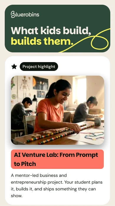
A mobile-first newsletter for an edtech platform that connects mentors with students who like project-based learning. A parent can read it in two to three minutes.
Team of 3 · built · demo newsletter, sample content
- Problem
- BlueRobins wanted a newsletter parents would read to the end: short, and made for a phone.
- My part
- Chose and sketched the five sections, proposed the quiz, made the wireframe and presented the pitch video.
- Design decisions
- Five short sections that read in two to three minutes on a phone, with a quiz section I proposed.
- Result
- Winner of the UC LAUNCH Launch-a-thon 2026, one of 4 winning teams out of 23.
A newsletter designed to be read in two to three minutes
BlueRobins connects mentors with students who learn by building. They wanted a newsletter, and we designed it in one build session: phone first, short to read, true to the brand.
- Mobile firstDesigned for the phone screen before anything else.
- On brandFollows the BlueRobins identity and design guidelines.
- Every section looks differentSo the issue stays varied from top to bottom.
- Fun, not childishPlayful enough to enjoy, grown-up enough for a parent.
Who to write for, and what goes in
- Students
- Parents
- Schools
- Mentors
- Advisors
For every candidate section I decided whether it would run every issue, rotate, or stay out. Five made it in.
- People: round photos
- Projects: rectangles
- Words: quotes
- Numbers: graphs
From a whiteboard to a phone screen
- 1BrainstormSections kept, rotated or dropped
- 2SketchEach section drawn as a block
- 3WireframeMade with Claude and Figma
- 4PolishSmall design changes in VS Code
- Chose the sectionsBrainstormed the options and decided which ran every issue.
- Sketched themEach section drawn as a different block.
- Proposed the quizMy main idea: a question for the family, always on.
- Mocked up the designA wireframe made with Claude and Figma, at phone width, and the demo newsletter.
- Presented the videoI was the voice and face of the pitch.
Scroll the phone, or jump to a section

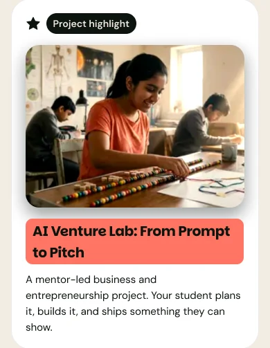
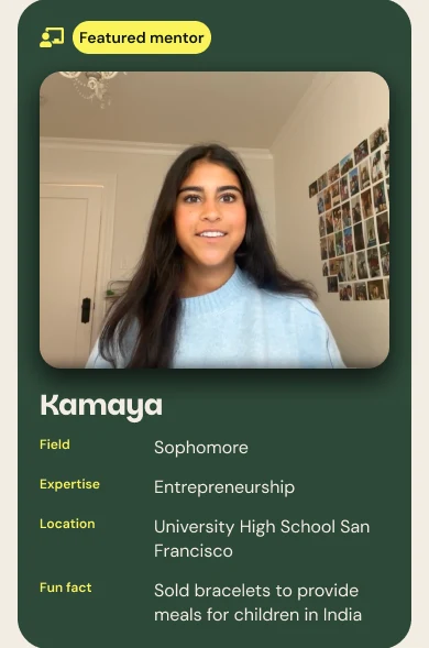

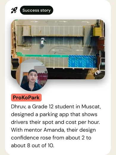
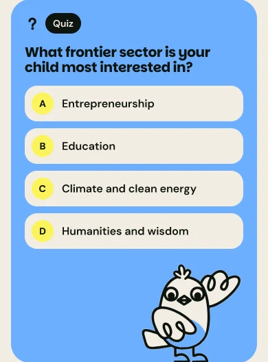
The photos and quotes are sample content. The layout is what we designed.
Winner of the Launch-a-thon
Winner of the UC LAUNCH Launch-a-thon, Fall 2026, as part of the BlueRobins team: one of 4 winning teams out of 23. The awards were on Sunday 4 October.
The newsletter is a demo with sample content, built in one session. Next step: test it with real parents to find out which sections they would read to the end.
Hands‑Free Book Page Turner
A device that turns the page of a paperback when someone presses a switch or a pedal. We designed it for people with limited dexterity.
Team of 3 · CAD design, drawings and BOM · 2nd of 5 finalists
- Problem
- People with limited hand dexterity cannot turn a page, and automatic page turners cost $2,000 to $3,000.
- My part
- Owned the concept and its functions, apart from the electroadhesive page separator. Modelled the base, tilting back and on/off button, and produced the drawings, exploded view and BOM.
- Design decisions
- Designed to be injection moulded in ABS. The base is two halves, so the tilter and back drop in before they are joined, and the pad and servos are off the shelf.
- Result
- 2nd of five finalists at The CAD Challenge 2026, with an internship interview at Hestus.
Turning a page takes a pinch, a grip and steady pressure
Arthritis, ALS, cerebral palsy and stroke can take that motion away, while a foot, head or chin still moves well. Mouth sticks need precision; automatic turners cost $2,000 to $3,000.
How might we help people with limited hand dexterity turn book pages independently, safely and without assistance?
3 hands-free ideas, 1 Pugh matrix
I introduced the double diamond to the team and set up the Pugh matrix to converge, scoring seven criteria from ease of use and safety to cost and ergonomics. I proposed two of the three starting ideas, the hair brush and the ponytail tier.
- The gap we sawA printed turner's arm blocked the page and its friction marked it. "Book Time" worked but was dear and built for magazines.
The base, the tilting back and how it is made
I modelled the body that holds the book, then wrote down how it is made and put together. The back tilts up to 70°. In the model the angle is set by hand, and the motorised adjustment the team planned is still to be modelled.
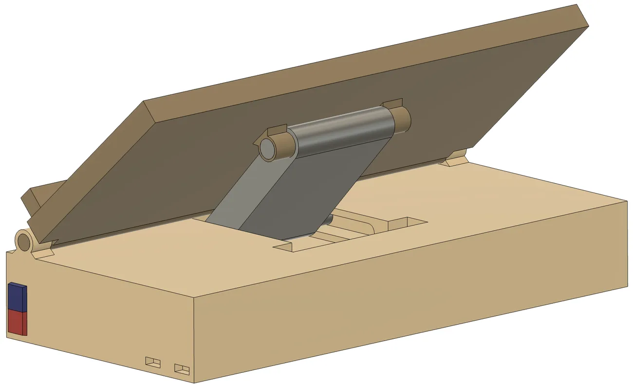
- Tilting back. It holds the book and is designed to tilt up to 70°. The angle is set by hand in the model.
- Tilter link and hinge. They carry the back and hold its angle.
- Recess in the base top. The tilter seats in it, which is why the back and tilter go in first (assembly step 1).
- Base housing. Made as two halves joined together (step 2), which should make it easier to mould.
- On/off button. It is colour-coded and also carries a text label, so it does not rely on colour alone.
Materials, processes and assembly
| Part | Material | Why | Made by |
|---|---|---|---|
| Base, back, tilter, flipper | ABS | Light, cheap, common for plastic housings | Injection moulding |
| Electroadhesive pad | Copper on Kapton film | Copper carries the power cheaply; Kapton withstands the voltage | Off the shelf |
| Links and attachments | Aluminium, stainless fasteners | Light, corrosion resistant, low friction | Off the shelf |
- 1Fit the back and tilter into the base.
- 2Join the two base halves, which should make it easier to mould.
- 3Build the separator and flipper.
- 4Join them and attach to the base.
- Calm to look atI chose neutral colours and a different colour for the moving parts, so they are easy to tell apart.
- Labelled for colour-blind usersThe on/off button carries a label as well as a colour, so it does not rely on colour alone.
- Easy to live withA wrist cushion, adjustable pedals, a box with handles and a strap, and different colours for the left and right buttons.
The pad lifts the page, the flipper carries it across
Team design. The video loads from YouTube only when you press play, or watch it on YouTube.
- LiftAn electroadhesive pad, copper electrodes under a film, pulls one page to the pad when it is switched on.
- CarryA flipper slides under the gap and carries the page across. It works in both directions.
- TriggerAny single-action switch: hand buttons, foot pedals or a mouth-pressure actuator.
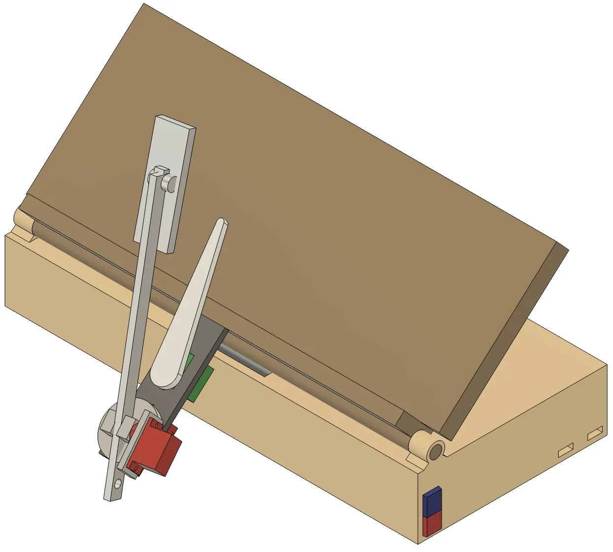
- Tilting back (mine). It holds the book.
- Base (mine). It carries the back and the module at its side.
- Separator arm (team). Its electroadhesive pad lifts one page.
- Flipper (team). It slides under the gap and carries the page across.
- Servo (team). One of the servos that move the arm and the flipper.
The flipping module is replaceable for repairs and upgrades. A master sketch checked how the parts interact before modelling.
2nd of five finalists, with a prototype as the next step
Next step: build a prototype and measure how reliably the pad lifts exactly one page.
- ResultSecond place at The CAD Challenge 2026, one of five finalists. The prize included an internship interview with Hestus.
- Known limitsThe pad surface wears, a wet page weakens the hold, and a bigger battery means a heavier base.
- NextBuild a prototype to check that the electromechanical system works.
Sources and assumptions. The 19.9 million figure is from the US Census Bureau (2012). The $2,000 to $3,000 price of automatic turners is quoted in our report. Pugh scores come from the team's matrix against the hair brush as reference. Book size and weight limits are our design targets, not measurements.
MedUp Prescription Pick-Up Locker
A locker inside supermarkets where people collect prescriptions outside pharmacy hours. A six-person concept study: I ran concept selection and the technical feasibility, sizing the cooling, battery and materials.
Team of 6 · concept study, sized by hand
- Problem
- Pharmacies cut their opening hours, so working people struggle to collect prescriptions.
- My part
- Ran concept selection with four Pugh matrices, then sized the drawers, cooling, backup battery and materials.
- Design decisions
- Sized the cooling and the battery together: 13 W leaks into the cold section, so the compressor runs about 4% of the time, and a 12 V LiFePO4 battery covers a 3-hour power cut.
- Result
- A supermarket locker concept of 120 drawers, 18 of them refrigerated.
Pharmacies close early, so working people miss their medicine
How might someone collect a prescription at a time that suits their day, without a pharmacist standing there all hours?
Four choices, each settled with a Pugh matrix
Concept generation and selection was my section of the report. For each choice I scored the options against a reference.
Drawers: easy to automate, accessible, and sturdy when open.
Supermarkets: shoppers already visit, and indoors helps refrigeration and security.
Spring latch: simple, cheap and still safe in an electrical failure.
QR code: private, non-invasive and cheap, with a backup number code.
Each criterion is scored from −2 to +2 against a reference option, and the scores are added up.
Sizing, cooling, power cuts and materials, by hand
The technical feasibility was my section of the report: how big the locker is, how it stays cold, how it survives a power cut and what it is made of.
Sizing: 120 drawers a locker
The market inputs come from the team's market analysis. I used them to size the drawers.
Keeping it cold: 13 W leaks in
2 min 33 s of every hour at full power
- Held at 5 °CThe middle of the 2 to 8 °C range for medicine. Shop assumed at 25 °C.
- R290 refrigerantZero ozone depletion and very low global warming impact.
- About 3 p a dayCompressor electricity at 27.69 p per kWh.
Power cuts: three hours of backup
- 3 hours of backupUK power cuts average about 2.15 hours, so there is a margin.
- 12 V LiFePO4Chosen over sealed lead acid: its capacity holds up at higher discharge rates.
- Denser and longer-livedDenser than lead acid, which matters in the base, and a much longer cycle life.
Materials and making
- 304 stainless steelRust resistant, hygienic and secure. Laminate was dearer and heavier.
- 1.52 mm and 1.22 mmChassis and drawer-wall thickness, from standard sheet gauges.
- Clear acrylic bottomsYou can see nothing is left in an upper drawer.
- TIG weldingPrecise on thin sheet. Strength against break-ins is a design target for the next stage.
- Built to be reusedRecyclable steel, a target 20-year life and swappable parts.
A locker inside the supermarket you already visit
The concept is the team's. A patient gets a one-time code when their prescription is ready, and collects it while shopping.
- 1Prescription readyThe patient gets a one-time QR code
- 2Go shoppingLockers sit inside supermarkets
- 3Scan the codeOr type a backup number
- 4One drawer opensA spring latch releases that drawer only
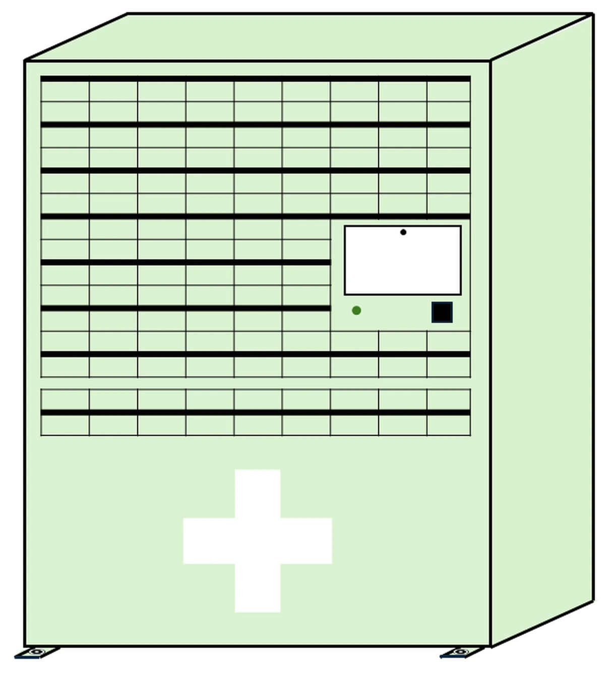 1234
- 102 ambient drawersSized to the largest UK medicine carton
- Screen, QR scanner, keypadSpeaker, camera and help button too
- 18 refrigerated drawers, 2 to 8 °CLowest, so everyone can reach them
- Compressor and 12 V backup batteryIn the base, with a power-cut alarm
- About 161 cm tallAn average UK woman's height
A concept study, with the cooling and battery sized by hand
Next step: build a prototype to measure the heat leak and the battery life. The chosen compressor is rated 305 W against the 13 W the cold section needs, so the report recommends a smaller cooling method as the next design step. Demand, prices and the NHS and supermarket partnerships are planning assumptions.
Sources and assumptions. Pharmacy statistics are from the Company Chemists' Association and the Royal Pharmaceutical Society, as cited in the team report. UK power-cut length is a UK-wide average, not a Bristol figure. Heat leak, compressor duty and battery sizing are my hand calculations from supplier datasheets.
What to Wear Website
A website that suggests outfits from the weather, your body and the clothes you own, and tells you what to pack for a trip.
Built · working website · I decided every feature, AI wrote the code
- Problem
- Deciding what to wear depends on the weather, how you feel the cold and what you own.
- My part
- Decided every feature and how the website works. AI wrote all the code.
- Design decisions
- Four tabs, You, Wardrobe, Today and Trips. Outfits come from the weather, your body and your wardrobe, and a trip becomes a packing list.
- Result
- A working website, shown here in screenshots with sample data.
It picks the outfit, so you don’t have to look at the sky
A website that suggests what to wear from the weather, how warm you run and the clothes you actually own, and tells you what to pack for a trip.
- YouHow warm you run and your skin tone, set once.
- WardrobeOnly the clothes you own, so nothing is suggested that you don’t have.
- TodayThe forecast, three looks for the day, and a look for each time you are out.
- TripsA packing list from the real weather your dates had in recent years.
Two answers that change every suggestion
I decided what the website should know about you before it suggests anything: how you feel the cold, and what you own.
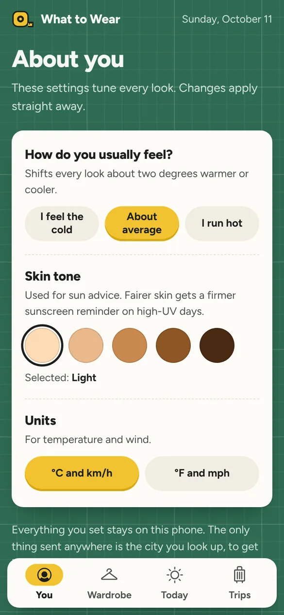
- How you usually feelCold, average or hot. It shifts every look about two degrees warmer or cooler, because some people feel the cold at 18 degrees and others are warm at 12.
- Skin toneUsed for sun advice. Fairer skin gets a firmer sunscreen reminder on high-UV days.
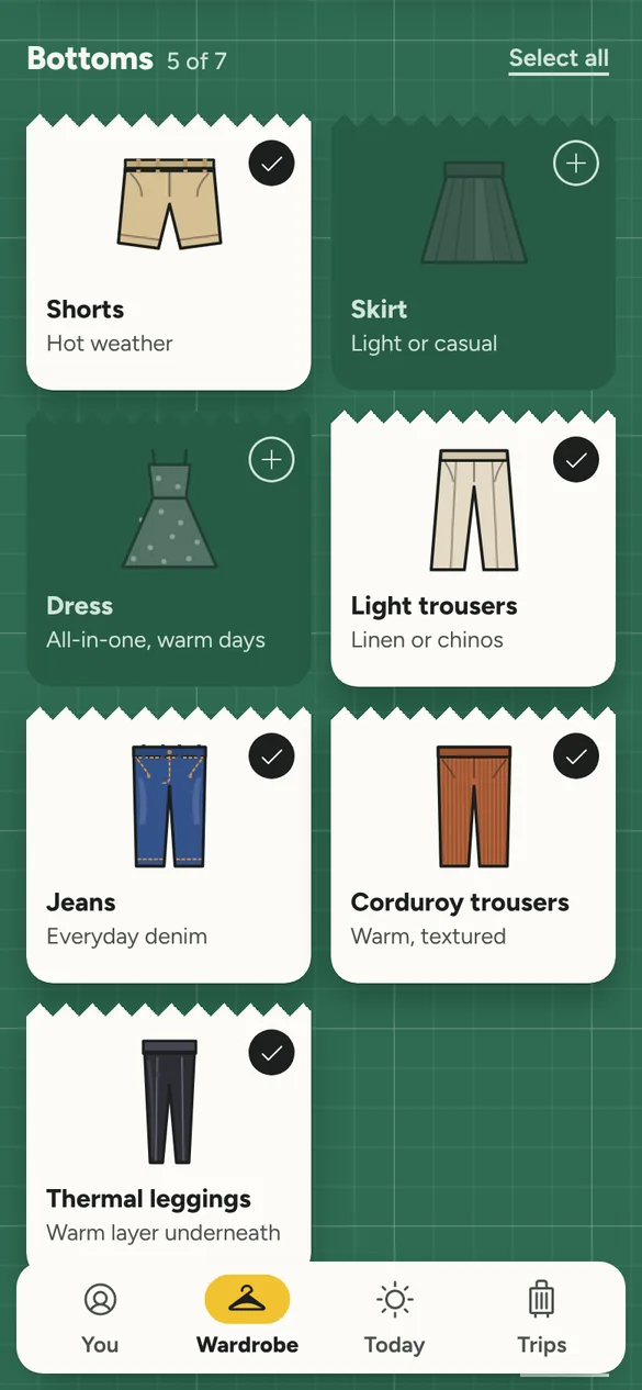
- 35 pieces, 6 groupsTops, layers, coats and jackets, bottoms, shoes and extras, each drawn as a flat illustration.
- Tap what you don’t ownEverything starts selected. Untick a piece and it is never suggested. Here the skirt and the dress are unticked, so you are never told to wear a dress you don’t own.
I decided what it does; AI wrote the code
I decided every feature and how the website works. AI wrote all of the code.
- What I decidedThe four tabs, what the website asks you, how warm you run shifts every look, which clothes count as yours, and how a day or a trip turns into outfits.
- What AI didIt wrote the code that makes the website behave that way.
Today and Trips, as the website shows them
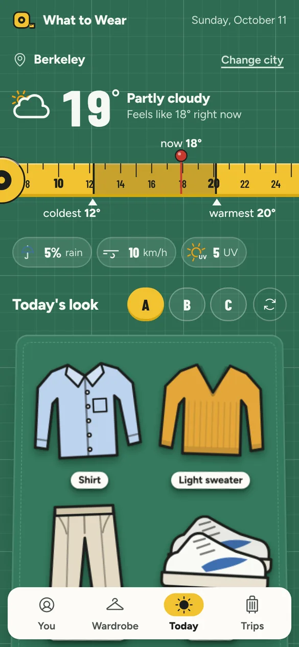
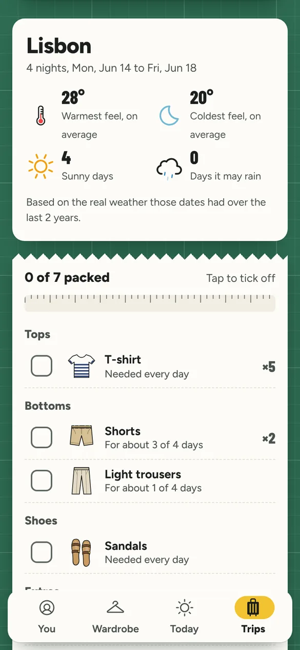
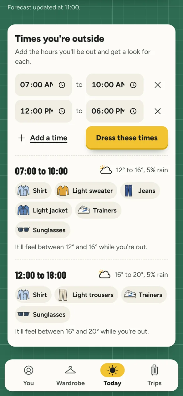
- The forecastTemperature, how it feels, rain, wind and UV, with a measuring tape from the day’s coldest to its warmest.
- Three looks, A, B and COutfits built only from the clothes you own, with a tip such as taking the light sweater off once it warms up.
- Times you’re outsideAdd the hours you will be out and get a look for each. A cool morning gets a jacket and jeans, a mild afternoon gets light trousers.
- 1DestinationWhere you are going
- 2DatesWhen you leave and come back
- 3Real weatherWhat those dates were like in recent years
- 4Packing listCounts per piece, to tick off
- Weather those dates hadWarmest and coldest feel, sunny days and days it may rain, from real weather on the same dates in recent years.
- Counts, not just a listIt says how many to take, such as five t-shirts, and why, such as shorts for about three of four days.
A working website, shown with sample data
The website works and you can try it with the button at the top of this page.
The screenshots use sample data: the weather for Berkeley and a four-night trip to Lisbon in June. I decided what the website does, and AI wrote the code. The next step is to have other people use it and learn from what they do. I would like to turn it into a mobile app one day.
Anthropometric Tendon-Driven Prosthetic Hand
The 5-person team built a hand where one cable closes all five fingers.
I tested and simulated how the fingers open again, building on the earlier design the team was improving: elastic resin, TPU and torsion springs, in 3D prints and Siemens NX simulations.
Team of 5 · graded individually · simulated, plus printed prototypes
- Problem
- Myoelectric hands cost £25,000 to £60,000; printed hands are cheap but need a passive way to open the fingers again.
- My part
- Led the printing and testing of elastic extensors, redesigned the MCP extensor and simulated two torsion spring designs in Siemens NX.
- Design decisions
- Moved from elastic resin to TPU, then used the simulation to find why TPU did not restore the finger, and simulated two torsion spring designs to see whether they open it.
- Result
- Failure diagnosed in simulation, and both torsion spring designs open the finger in simulation.
Good hands cost a fortune, cheap hands barely grip
About 5,200 upper-limb amputations happen in the UK each year. Myoelectric hands cost £25,000 to £60,000. Printed ones are affordable, but weak.
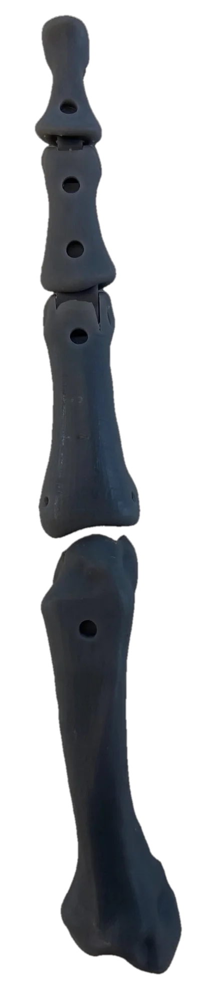
The team's hand closes all five fingers with one cable. My job was the other half of the motion, how the fingers open again: a tendon pulls the finger closed through three joints, and something passive has to pull it open without fighting the grip.
Show the finger, labelled
Elastic extensors first, then springs
To open the finger again we tried elastic extensors, in two printed materials, before moving to torsion springs.
Elastic resin 50A
Too soft. Six prints tore, supports would not come off, and the simulation would not converge.
✗ DroppedTPU 90A
Stiffer, and it printed cleanly for the ring and middle fingers. Inserts deformed, but the material was worth simulating.
✓ Simulated nextTPU opened the finger on paper but held the wrong tension through the motion (next tab). Torsion springs, a different way to open it, were the next option to simulate.
I simulated whether TPU, then springs, could open the finger
My streams were printing and testing the passive extensors, redesigning the MCP extensor, and simulating two torsion spring designs in Siemens NX.
Can TPU open the finger after it grips a tennis ball?
Ring finger, 66 mm tennis ball at the optimal grasp. Flexible-body extensors (1.6 to 1.9 mm tetrahedra), springs driving the motion, 1.2 s simulated.
| Stage | Beginning | Middle | End |
|---|---|---|---|
| What the MCP extensor should carry | No tension | Some tension | Some tension |
| What it carried | High tension ✗ | High tension ✓ | No tension ✗ |
Simulated stressTensile strength (reference)
Redesign: cut the links that held tension at rest
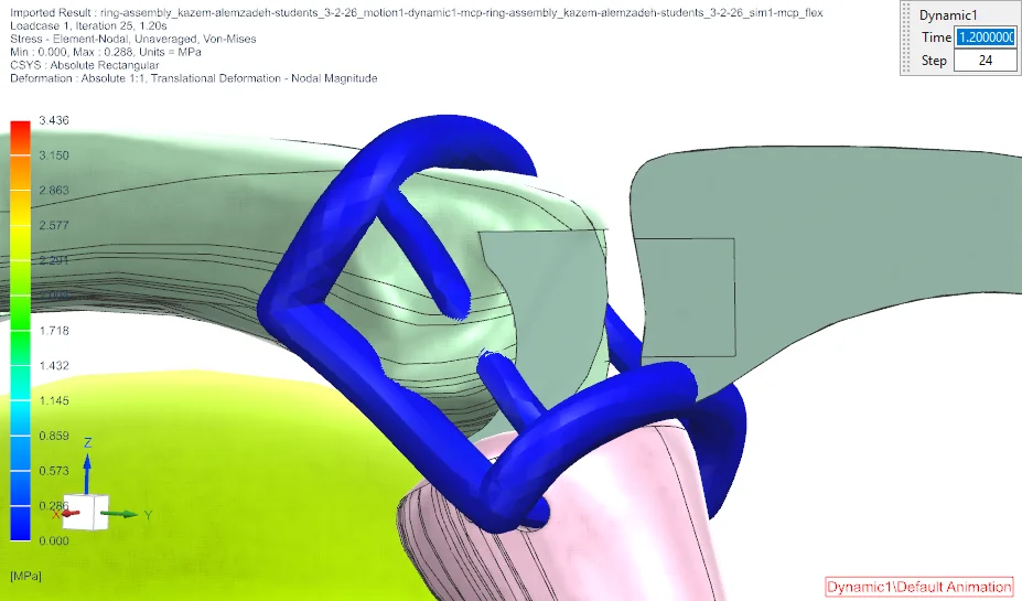
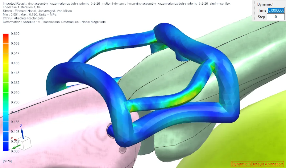 Original · start
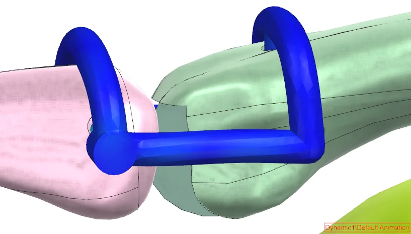
 Original · end
 Cut · start
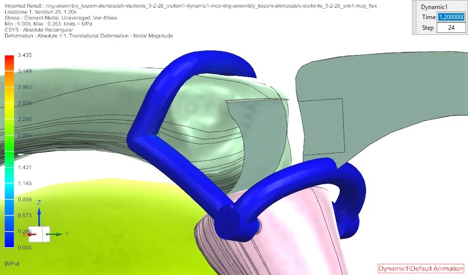 Cut · end
- Tension held at rest. The ringed links are under load before the finger moves (up to 0.62 MPa), which fights the grip.
- Slack at the end. Nothing is left pulling, so it cannot open the finger.
- Fixed at rest. With the links cut there is no tension before the grip.
- Slack at the end. The redesign fixed the initial tension, and the slack at the end led me to recommend extensors that follow the bones’ curvature more closely.
| Stage | Beginning | Middle | End |
|---|---|---|---|
| Should carry | No tension | Some tension | Some tension |
| Redesign carried | No tension ✓ | Some tension ✓ | No tension ✗ |
Fixed at rest, still slack at the end. I recommended extensors that follow the bones’ curvature more closely, and moved on to springs.
Two torsion spring designs, simulated on one finger
One torsion spring at the DIP joint and two at the PIP. Design 1 is preloaded; design 2 scales the bones 1.5 times, so it is bigger than a human hand, because the 5 mm bearings and the springs had to fit.
The team's hand: one cable, under 400 g
The group built a prototype hand. Everything on this tab is the team's result, not only my part.
- One cableA single tendon closes all five fingers.
- Under 400 gThe weight of a biological hand, which was our ceiling, and the prototype stayed under it.
- Two graspsThe prototype demonstrated power and pinch grasps.
I simulated the two spring designs in Siemens NX. The next step is to print them, fit them to the prototype and test the grip.
Both spring designs open the finger in simulation; grip is the next test
Simulated stressSupplier ultimate tensile strength (reference)
Both designs open the finger in simulation. Next step: test the grip on a physical prototype. The springs are stiffer than the analysis needed, which adds resistance to closing, and design 2 is scaled 1.5 times.
Original extensors (1,636 N)Torsion springs, design 2 (1,556.5 N)
Sources and assumptions. Amputation numbers, hand prices, grip forces and abandonment rates come from the sources cited in the group report. Stresses and forces are Siemens NX simulation outputs for one finger, not measurements. The 2,420 MPa figure is the spring supplier’s ultimate tensile strength, used as a reference, not a yield limit.
Tent Thermal Management
A two-person tent on a cold UK night loses 4.0 kW of heat, and heating has to make up 3.9 kW. I modelled where it goes, then found three passive fixes that cut the need by 82%.
Individual · hand calculations
- Problem
- Keep two sleepers at 19 °C in a thin tent on a −2 °C night without adding much mass or complexity.
- My part
- Modelled conduction, convection and radiation for a two-person tent by hand.
- Design decisions
- Modelled the tent as a box and listed 27 assumptions, most leaning to the worst case. Chose three passive fixes that need no power.
- Result
- The three fixes cut the 3.9 kW of heating needed by 82%, to 706 W, which still needs a heater.
Hold 19 °C inside a thin tent on a −2 °C night
A light tent is fully exposed to wind and cold. The job: keep two sleepers warm on a UK winter night without adding much mass, bulk or complexity.
Two people in a Vango Banshee 200, a popular budget two-person tent.
A box, two sleepers and 27 stated assumptions
I modelled the tent as a 2.3 × 1.3 × 0.75 m box with the two sleepers as the only source, about 150 W between them, and worked out each way heat leaves by hand.
Conduction, convection and radiation use Grashof, Reynolds, Prandtl and Nusselt number correlations. Most of the 27 assumptions lean to the worst case, and my report marks each as an over- or underestimate, so the result is a conservative estimate.
The tent loses 4.0 kW, mostly on the wind
The tent loses 4.0 kW. The two sleepers give back about 150 W, so heating has to make up 3.9 kW, 26 times what they give.
My model, worst casePublished study
Three passive fixes cut the loss by 82%
Loss without the fixLoss left with it
One cold night, two average people
Next step: test on a real night. Each fix was calculated on its own with the tent surface held at 19 °C and the results were added together, so the 82% is an estimate. About 706 W of heating is still needed with the three passive fixes. A real test would use a specific tent, people of different sizes and temperature logging through a night, and would add sleeping bags, clothing, changing weather and condensation to the model.
Sources and assumptions. The net 3.9 kW is the 4.0 kW lost minus about 150 W from the sleepers (the report gives 149 W). The 1.37 kW comparison is a published army-tent study scaled to two people. The tent model, the 27 assumptions and every loss figure are my hand calculations.
Pressure Vessel Lifting Lug
Is a welded lifting lug safe for a 12-tonne pressure vessel? I checked it by hand, in Abaqus, against a pull off-axis, and for fatigue, then set an inspection interval.
Individual · hand calculations and Abaqus FEA
- Problem
- Can a welded lifting lug carry its share of a 12-tonne pressure vessel, and how often must it be inspected?
- My part
- Built the hand model, checked it in Abaqus, searched for the worst off-axis pull and proposed the inspection interval.
- Design decisions
- Checked the weld and the eye separately, used the worst off-axis pull instead of the straight pull, and let fracture mechanics set the inspection interval.
- Result
- Yield-to-stress ratio of 5.6 at the weld and 2.7 in the eye. Inspection proposed every 10⁵ cycles.
Will a welded lug survive lifting a 12-tonne vessel?
Six lugs share the weight of a pressure vessel, and each is welded to a plate that is welded to the vessel. I checked one lug for strength, for a pull that is off-axis, and for fatigue, then proposed an inspection interval.
One element by hand, checked against Abaqus
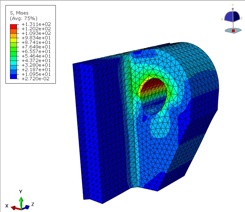
A six-node triangle solved by hand, checked against a converged Abaqus mesh (C3D10 elements, 4 mm).
- Plane stressThe hand model treats the lug as a flat sheet and ignores the fixed back plate, so it cannot capture the eye.
- LoadThe ×3 safety factor is already inside the 58.86 kN, so no further factor is applied.
- Constants from the course briefFracture toughness KIC 60 MPa√m, geometry factor Y = 1.12, and Paris' law constants C = 10⁻¹¹ and m = 4 were given, not measured.
Two models agree, and a pull off-axis is the worst case
The two models agree closely on how far the lug moves.
What if the cables pull off-axis?
- 130.7° worst direction: 305.3 MPa of extra stress makes the weld yield
- 131.7° where a strain gauge reads 1.843×10⁻³, almost the critical 1.85×10⁻³
Misaligned cables and a swinging vessel add stress. I searched every direction for the one that yields the weld with the least extra stress, and put the strain gauge where it would see it first.
Yield-to-stress ratio of 5.6 at the weld, 2.7 at the highest-stress point
- 57.31Hand model, at the load point
- 63.22Abaqus, at the weld
- 131.1Abaqus, peak inside the eye
- The load goes through the eye. 58.86 kN per lug, safety factor included. The highest stress is here, 131.1 MPa, a yield-to-stress ratio of 2.7.
- The weld joins the lug to its plate. 63.22 MPa, a ratio of 5.6. This is the stress range I used for the fatigue calculation.
- The calculation that follows. A crack growing from the smallest one an inspection finds (1.46 mm) to the allowed size (4.05 mm) takes 1.77×10⁵ cycles, so I proposed inspecting every 10⁵ cycles.
Fatigue: a proposed inspection interval comes before the crack reaches its allowed size
Hand calculations and Abaqus FEA, and what comes next
Every number here comes from stress and statics analysis and Abaqus simulation. The inside of the eye carries the highest stress, and repeated lifts could crack it. Next steps: a dynamic analysis to find the natural frequencies to keep the lift away from, and a physical test of a welded lug to check the model.
Sources and assumptions. Load, material properties, KIC and the Paris constants come from the course brief. Stresses and displacements are my hand calculation and an Abaqus CAE model. The proposed inspection interval and cycle counts come from the coursework Paris' law model and are not fatigue tests.
Solar Panel Deployment Mechanism
A scissor mechanism that unfolds six solar panels from a car roof box on one DC motor. The brief was a course scenario set as if for a roof-tent company, and I led the team of four.
Team of 4 · led · designed and calculated
- Problem
- Can a car roof box hold six solar panels that deploy themselves on one DC motor and face the sun?
- My part
- Led a team of four. Wrote the 42-requirement specification, built three of the four LEGO concepts and designed the failsafe automation.
- Design decisions
- Compared the concepts in LEGO, then tuned the link lengths and mounting angles of the chosen one so the panels face the sun.
- Result
- It met all but one key requirement in the calculations: 8.17 kg against a 30 kg limit and a 10.65 s deployment. The packed height was too tall.
Pack flat on the roof, open to face the sun
A course brief, set as if for a roof-tent company, asked: can a car roof box hold a solar system that deploys itself and faces the sun?
- One DC motor unit on the 12 V car battery
- Clamps to standard roof bars
- Runs only while parked
- Packs flat to cut drag
We built the linkages in LEGO before choosing
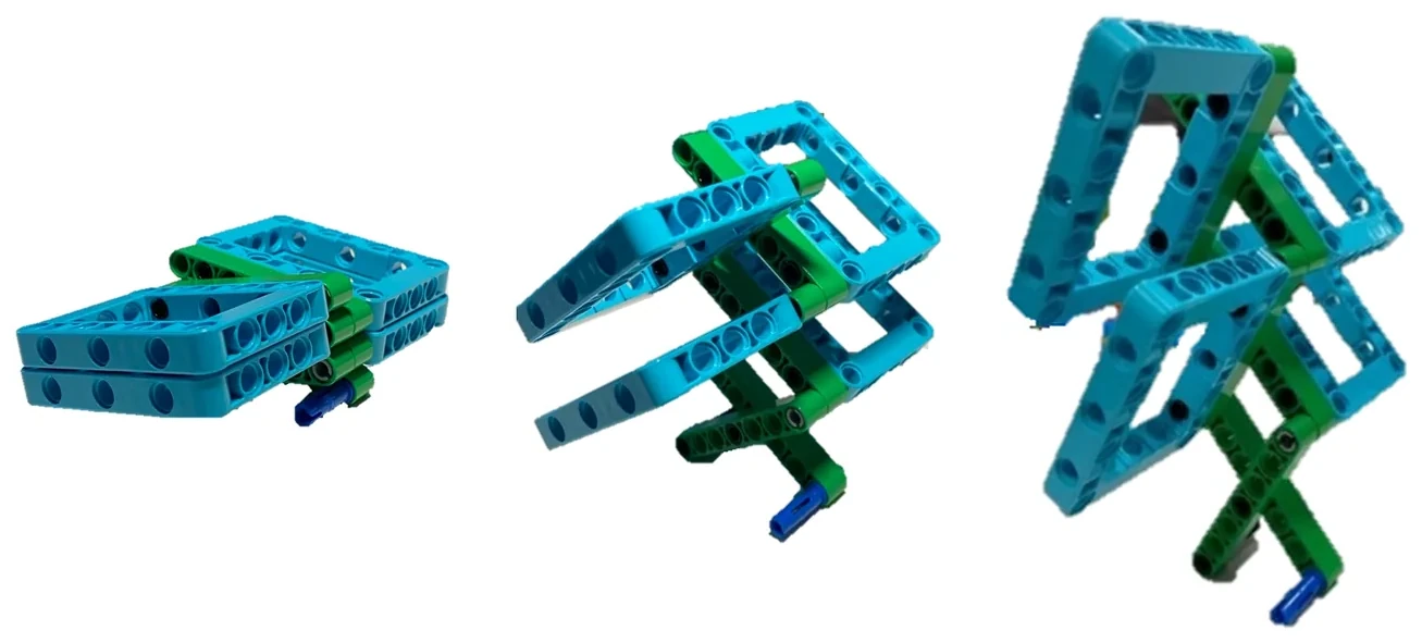
I built three of the four concepts in LEGO, including the one we chose.
Concept 1 · Scissor and extending beam
Panels pack vertically. 0 to 90°.
Concept 2 · Sliding panels
Panels slide into slots. About 50° at most.
Concept 3 · Simple scissor Chosen
Panels sit on the arms. 4 to 6 panels, 0 to 80°.
Concept 4 · Gear parallelogram
Sweeps past vertical, to about 100°.
How we chose
A Pugh matrix scored each concept against criteria taken from the specification: manufacture and assembly, usability, panel performance, deployed panel area against packed volume, and speed. Concept 3 won because one scissor lifts several panels with few parts, only beams and screws, and it deploys fast and packs small.
A proposed failsafe that stops the motor, even with a button held
As team lead I wrote the specification and built the LEGO concepts. Then I designed the supervisory controller, chose its sensors and wrote the Arduino interlock code. The motor runs only while all three hold:
- OpenOne press runs it fully open, then it stops.
- CloseThe same, the other way.
- Change of mindThe opposite button mid-way stops it, waits, then reverses.
Next step: run the failsafe code on an Arduino, with decimal variables and scaled sensor readings for the 0.03758 and 1.526 thresholds.
Two scissors, a driveshaft and three rows of panels
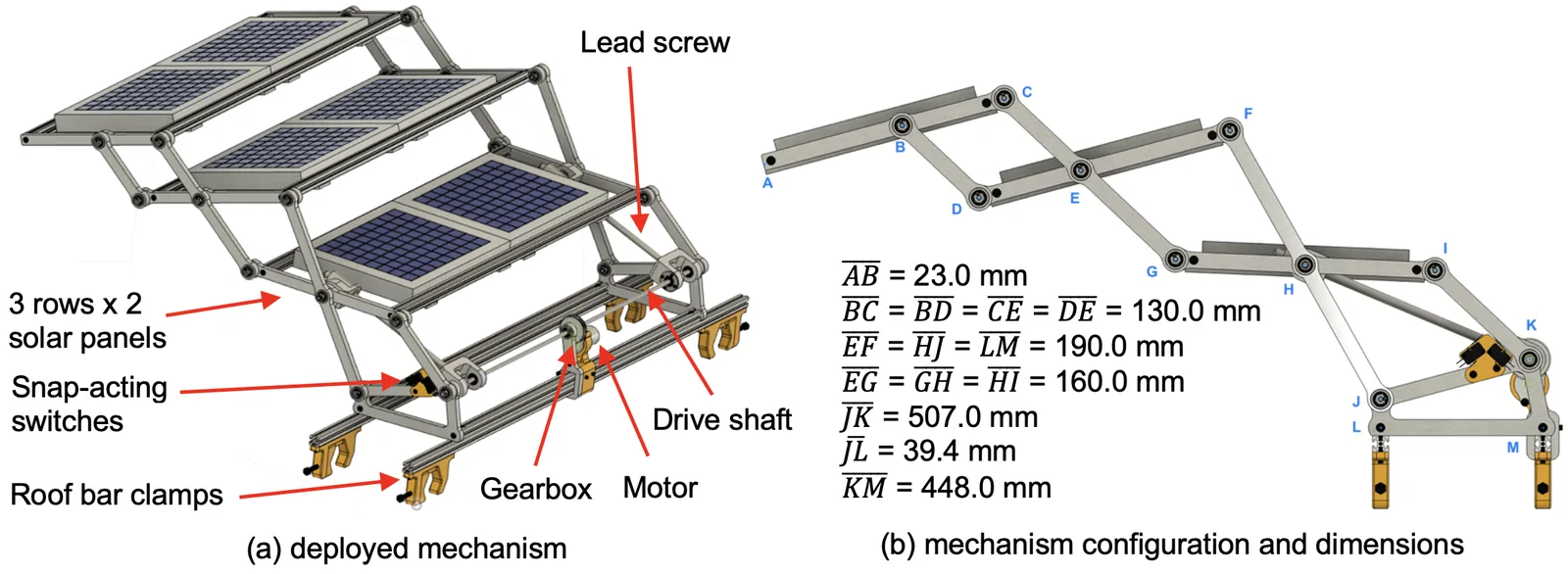
The final design is the team's. Two scissor mechanisms sit on the sides, joined by a driveshaft, with three rows of two panels between them.
 LEGO concept 3
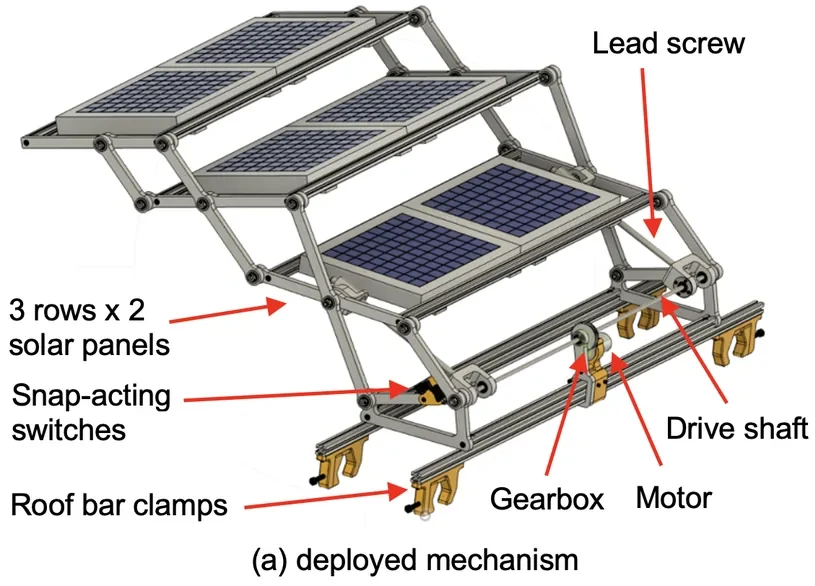 Final design
- Kept: a scissor of beams that carries the panels. This is why concept 3 won, and it is still the heart of the final design.
- Changed: two scissors, one on each side, with three rows of two panels between them, for rigidity and more panel area.
- Added: a drive shaft joining the two sides so they move together.
- Where the geometry was first tuned. LEGO let us change linkage lengths and mounting angles quickly. In the final design the lengths changed again, to point the panels more squarely at the sun.
- Lighter panelsSmaller 1.4 kg panels brought the deployed height from 3 m to 0.80 m.
- A vertical lead screwIt cut the force needed to start from 20,000 N to 143.7 N, and it is self-locking.
- Aluminium beamsAA6061-T6, with a safety factor of 5.69, within a £50 material budget.
It met all but one key requirement in the calculations
ActualTarget
The packed height is set by the vertical lead screws. The car would still enter regular car parks (1.9 to 2.5 m) and stay stable below 80 km/h, according to the report. Next step: build the mechanism to check the calculated mass and deployment time.
Sources and assumptions. Figures come from the group design report (March 2025). The roof-tent company is a course scenario, not a real client. The specification, the Pugh matrix and the component choices are in the report's tables.